Description
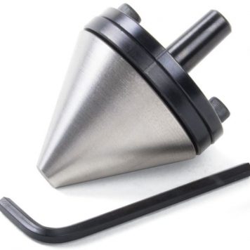
Sherline Adjustable Tailstock Bullnose Live Center 1205
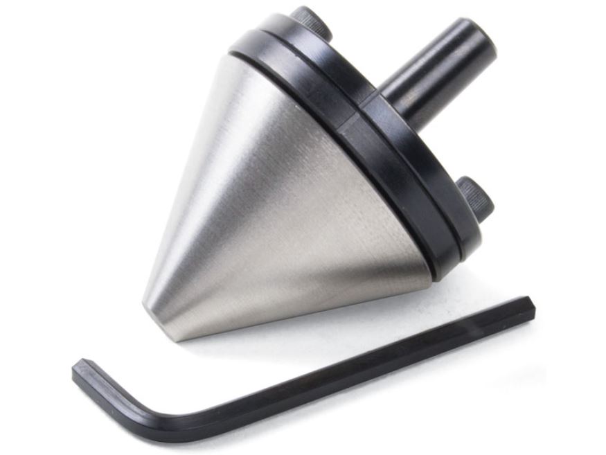
Adjustable Tailstock Bullnose Live Center
The Sherline Bullnose Live Center
The #1201 Adjustable Live Center is for use with solid parts with a drilled hole for centering. The #1205 Adjustable Bullnose Live Center is much larger and is designed to support parts with a large center hole or tubing. It accommodates a center hole from 3/8″ to 1-3/4″ diameter. The live center features two preloaded ball bearings inside.
A live center is held in the tailstock of a lathe and supports the unchucked end of the work while allowing it to rotate easily on a bearing, as opposed to a standard “dead” center that does not rotate. If the point of the center is not in perfect alignment with the shaft, or if the center mark on the part is not dead-on, the part will “run out” (vibrate or wobble), making precise machining impossible.
An adjustable live center allows you to precisely position the center. The center is attached to one plate, while the shaft is part of another. Two slightly oversize holes in one side allow adjustment screws to be loosened, the center located and then locked down where you want it. As a result, highly accurate centering can be achieved.
If ultimate accuracy is your goal, the adjustable live center will help you achieve it. The standard Adjustable Live Center is P/N 1201. It has a sharp 60° point to fit into a center drilled hole in the part to be supported.
The P/N 1205 live center is much larger and will support a part with a larger center hole or tubing from about 5/16″ ID up to 1-3/4″ ID.
The Purpose and Use of the Adjustable Tool Holders
The accuracy that is attainable by adjustable tailstock tools is governed by the amount of skilled effort you put forth. Consequently, only someone new to the machine trade would talk about “perfect” alignment. In the machine business, you talk tolerances even if you can’t measure an error. The error has to be assumed from the tolerances of your method of checking.
These holders are simple to use. The holders are divided into two parts with flanges. These flanges are bolted together with two screws. The clearance holes for these screws allow the front to be adjusted in relation to the rear. The rear section has a witness mark (groove). This mark should always be located at the top so the holder is located the same way in the tailstock each time.
| Shaft and Plate Material | 12L14 Steel |
|---|---|
| Shaft and Plate Coating | Black Oxide |
| Bullnose Center | Case Hardened and Ground Steel |


